3D simulator for metal extrusion
Overview
The 3D simulator enables the user to perform fast three-dimensional simulations of the extrusion process enabling one to compute stress and deformation, temperature and fluid flow. Numerical trials allows to select optimal CAD concepts. This leads to savings on correction costs and longer lifetimes of critical parts.
It has been automatized so that no prior knowledge of numerical simulation or methods is needed to perform simulations of complex cases.
It is based on the finite element method, which requires the generation of a mesh from a CAD file provided by the user.
It can be coupled with the automatic bearing calculator (ABC) in order to determine the geometry of the bearings.
)
)
)
)
Main tasks
Three main phases must be performed by the user:
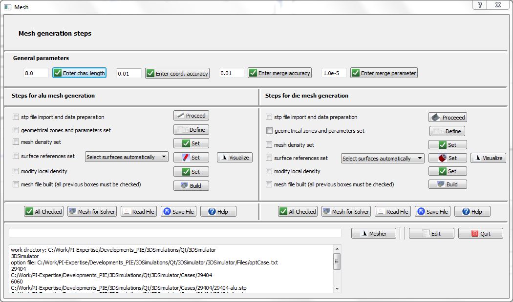
- A first phase dedicated to Input data and mesh generation when the input data like the die and contained aluminum alloy geometry provided in two separate step files and the operation parameters are loaded or specified via the visual interface. The mesh is built in a subsequent step.
- A second phase dedicated to data preparation for the various solvers and solver execution.
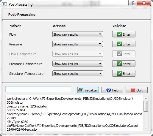
- A third phase dedicated to result data post-processing and visualization.
A GUI is provided for the user in order to proceed in an easy way to the mesh generation, field computations and data post-processing.

Versions
The current version available for users is 1.0, which runs on windows 7 and 8 and on various linux distributions. The next version 2.0 will encompass parallel computing on linux operating systems, symmetry comsideration and updated results after die deformation
Available solvers in version 1.0
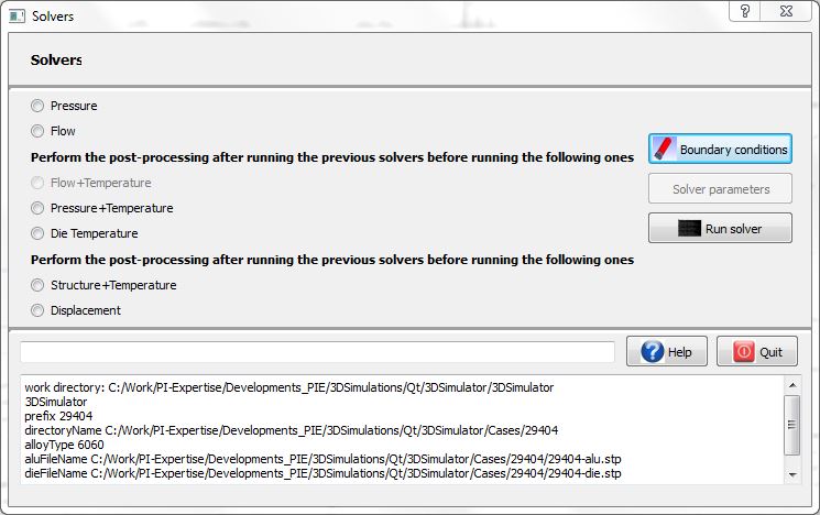
The available solvers in the 3D simulator are:
- 1: A flow solver that enables one to determine the aluminum flow at a specified average temperature. The ram velocity is imposed and free boundary conditions are considered at the profile exit.
- 2: A pressure solver that enables one to determine the aluminum flow at a specified average temperature. The output velocity is imposed and and free boundary conditions are considered at the billet-ram interface.
- 3a: A pressure solver that enables one to determine the aluminum flow while taking into account temperature effects, The output profile velocity is imposed and and free boundary conditions are considered at the billet-ram interface.
- 3b: A flow solver that enables one to determine the aluminum flow while taking into account temperature effects. The output profile velocity is imposed and and free boundary conditions are considered at the billet-ram interface.
- 4: A temperature solver that enables one to determine the average temperature field in the die.
- 5: A solid mechanics solver that enables one to determine all the relevant mechanical stress, strain rate and displacement quantities while taking into account temperature effects.
- 6: A displacement solver that enables one to determine specifically the displacement of the die due to mechanical loads in the presence of temperature gradients.
Performance examples
A 64 bit computer is necessary for cases where the number of mesh point exceeds about 1 million nodes due to the RAM limitation of windows for 32 bit computers.
The following typical performances on various computers are given in the following table.

Typical preparation and execution times of the various simulation steps for different computers.